- #SIEMENS STEP 7 TUTORIAL HOW TO#
- #SIEMENS STEP 7 TUTORIAL SOFTWARE#
- #SIEMENS STEP 7 TUTORIAL DOWNLOAD#
The Data Block is generated with a symbol Name. Open the data block DB1 with double click or open object. For Symbolic Name and Symbolic Comment is optional. Insert Data Block, in INSERT menu select S7 Block and then Data BlockĮnter the number for Data Block in Name and type (in this case I set DB1), choose Shared DB so DB can accessed by another program. Insert a new S7-Program, in INSERT menu select PROGRAM and then S7 PROGRAM Start from Step 1: Setup PG/PC Interface, Step 2: Create New Project and Step 3: Add Station Object
#SIEMENS STEP 7 TUTORIAL HOW TO#
How to Generate Data Blocks (DBs) in Simatic S7-PLCSimįollow Step 1 to Step 3 of the article about Learning PLC Programming With SIMATIC S7-PLCSIM For more detail you can see in table below 1 Bool have length 1 Bit, and 1 Byte have length 8 Bit. In the figure 2, 1 box represent 1 Bit memory.

This structuring of a DB follows through input in a table with the tool LAD, STL, FBD - S7 Block Programming.

BOOL or WORD) can be saved in arbitrary order. Global DBs, where all OBs, FBs and FCs read all saved data or can even write in the DB and local instance DBs, which are assigned a particular FB. Your hard disk contains up to 8 Kbytes(8192Bytes) space.
#SIEMENS STEP 7 TUTORIAL DOWNLOAD#
+ Download Automating with SIMATIC S7-1200 by Step7 Basic + WinCC Basic.Data Blocks (DBs) can be used by your program to save data in the CPU. > Link Download Ebook ( MEGA.NZ Link – Easy Download ) + 13 Online operation, diagnostics and debugging
#SIEMENS STEP 7 TUTORIAL SOFTWARE#
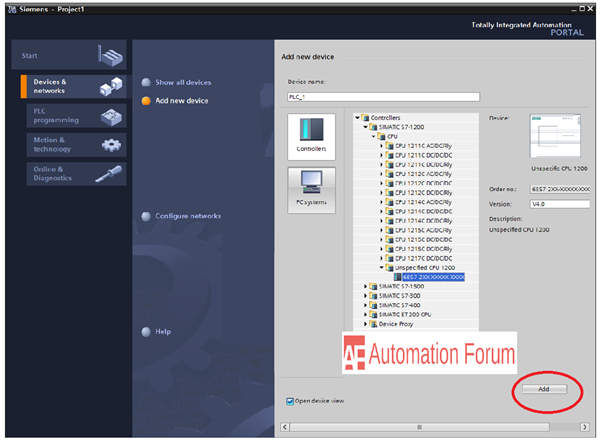
The description focuses on the generation of the control program using STEP 7 Basic engineering software Version 11 SP2. This book describes the S7-1200 automation system with S7-1200 programmable controllers and HMI Basic Panels. Modern and intuitive user guidance allows efficient and task-oriented engineering of control and visualization devices. The SIMATIC WinCC Basic configuration software included in STEP 7 Basic is used to configure the Basic Panels. STEP 7 Basic is the common tool for hardware configuration, generation of the control program, and for debugging and diagnostics. The STEP 7 Basic engineering software makes it possible to use all S7-1200 controller options. A touch screen with various monitor sizes and coordinated communication over Industrial Ethernet are ideal prerequisites for interaction with S7-1200. New SIMATIC HMI Basic Panels have been designed for operator control and monitoring appropriate to the S7-1200 programmable controllers, and provide a performance and functionality optimized for small applications.

Two established programming languages are available for solving automation tasks: ladder logic (LAD) and function block diagram (FBD). The technological functions integrated in the CPU module mean that extremely versatile use of the device is possible. Many small applications can be solved using the CPU module with on-board I/O. The S7-1200 programmable controllers are of compact design and allow modular expansion. This book describes the newly developed SIMATIC S7-1200 automation system.

These requirements are fulfilled by the SIMATIC automation system which provides uniformity for configuration, programming, data management and communication. The Totally Integrated Automation concept permits uniform handling of all automation components using a single system platform and tools with uniform operator interfaces. The SIMATIC automation system unites all the subsystems of an automation solution under a uniform system architecture to form a homogenous whole from the field level right up to process control.


 0 kommentar(er)
